Difference between revisions of "Differential RCS"
| Line 4: | Line 4: | ||
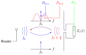
Details have been presented in <ref>N. Barbot, O. Rance, and E. Perret, [https://nicolas-barbot.ovh/wiki/pool/delta.pdf "Differential RCS of modulated tag,"] IEEE Transactions on Antennas and Propagation, pp. 1–1, 2021, early access. doi: 10.1109/TAP.2021.3060943.</ref> and can be seen as a complementary definition compared to the time definition. The basic idea relies on the decomposition of the RCS <math>\sigma</math> into a static RCS <math>\sigma_s</math> and a dynamic RCS <math>\sigma_d</math> and to pass into the frequency domain. Fig. 1 presents the main result where the (total) backscattered signal by the modulating UHF tag can be decomposed into 2 parts. Component located at <math>f_0</math> can be linked to <math>\sigma_s</math> whereas component located around <math>f_0</math> can be linked to <math>\sigma_d</math>. | Details have been presented in <ref>N. Barbot, O. Rance, and E. Perret, [https://nicolas-barbot.ovh/wiki/pool/delta.pdf "Differential RCS of modulated tag,"] IEEE Transactions on Antennas and Propagation, pp. 1–1, 2021, early access. doi: 10.1109/TAP.2021.3060943.</ref> and can be seen as a complementary definition compared to the time definition. The basic idea relies on the decomposition of the RCS <math>\sigma</math> into a static RCS <math>\sigma_s</math> and a dynamic RCS <math>\sigma_d</math> and to pass into the frequency domain. Fig. 1 presents the main result where the (total) backscattered signal by the modulating UHF tag can be decomposed into 2 parts. Component located at <math>f_0</math> can be linked to <math>\sigma_s</math> whereas component located around <math>f_0</math> can be linked to <math>\sigma_d</math>. | ||
Also, this frequency definition (as the original definition) is not limited to RFID tags and can be applied to any linear time-varying system such as rotating tags, moving tag and (surprisingly) barcodes. | |||
Another consequence is that linear time-invariant systems, are characterized by a delta RCS of 0. | |||
For a UHF tag, assuming that the chip can switch with a equal probability in-between 2 states characterized with <math>\Gamma_1</math> and <math>\Gamma_2</math>, and is connected to a half-wavelength antenna, the delta RCS <math>\sigma_d</math> can be expressed as: | |||
<math> | |||
\sigma_d = \frac{\lambda^2 G^2}{4 \pi} \frac{|\Gamma_1 - Gamma_2|^2}{4} | |||
<\math> | |||
At 915 MHz, this equation predicts a maximal delta RCS for passive (i.e., <math>\{\Gamma_1 = 0; \Gamma_2=-1\})</math> and semi-passive (i.e., <math>\{\Gamma_1 = +1; \Gamma_2=-1\})<math> UHF tags | |||
of -22 dBsm (63 cm<math>^2<math>) and -16 dBsm (250 cm<math>^2<math>) respectively. | |||
Measurement method is based on the measurement of the modulated PSD of the backscattered signal <math>S_R(f-f_0)</math> which can be directly estimated by any spectrum analyzer. Delta RCS can finally be expressed as: | Measurement method is based on the measurement of the modulated PSD of the backscattered signal <math>S_R(f-f_0)</math> which can be directly estimated by any spectrum analyzer. Delta RCS can finally be expressed as: | ||
| Line 13: | Line 25: | ||
where <math>2b</math> is the span of the instrument and <math>\epsilon</math> a constant allowing to remove the static contribution generated by the tag (and the environment). | where <math>2b</math> is the span of the instrument and <math>\epsilon</math> a constant allowing to remove the static contribution generated by the tag (and the environment). | ||
<references /> | <references /> | ||
Revision as of 15:08, 12 August 2021
Differential RCS characterizes the aptitude of a tag to modulate the backscattered power. This parameter is has been introduced by P. Nikitin for UHF tags [1] and is classically estimated based on the variation of the IQ channels of the two states of the chip in the time domain. This quantity can however be generalized for any modulating tag in the frequency domain. The frequency definition remains (almost) compatible to the time definition. Finally, this new definition allows to estimate the delta RCS of any tag accurately using a simple spectrum analyzer.
Details have been presented in [2] and can be seen as a complementary definition compared to the time definition. The basic idea relies on the decomposition of the RCS into a static RCS and a dynamic RCS and to pass into the frequency domain. Fig. 1 presents the main result where the (total) backscattered signal by the modulating UHF tag can be decomposed into 2 parts. Component located at can be linked to whereas component located around can be linked to .
Also, this frequency definition (as the original definition) is not limited to RFID tags and can be applied to any linear time-varying system such as rotating tags, moving tag and (surprisingly) barcodes. Another consequence is that linear time-invariant systems, are characterized by a delta RCS of 0.
For a UHF tag, assuming that the chip can switch with a equal probability in-between 2 states characterized with and , and is connected to a half-wavelength antenna, the delta RCS can be expressed as:
Failed to parse (unknown function "\math"): {\displaystyle \sigma_d = \frac{\lambda^2 G^2}{4 \pi} \frac{|\Gamma_1 - Gamma_2|^2}{4} <\math> At 915 MHz, this equation predicts a maximal delta RCS for passive (i.e., <math>\{\Gamma_1 = 0; \Gamma_2=-1\})} and semi-passive (i.e., which can be directly estimated by any spectrum analyzer. Delta RCS can finally be expressed as:
where is the span of the instrument and a constant allowing to remove the static contribution generated by the tag (and the environment).
- ↑ P. V. Nikitin, K. V. S. Rao, and R. D. Martinez, “Differential RCS of RFID tag,” Electronics Letters, vol. 43, no. 8, pp. 431–432, Apr. 2007.
- ↑ N. Barbot, O. Rance, and E. Perret, "Differential RCS of modulated tag," IEEE Transactions on Antennas and Propagation, pp. 1–1, 2021, early access. doi: 10.1109/TAP.2021.3060943.


![{\displaystyle \sigma _{d}={\frac {(4\pi )^{3}d_{1}^{2}d_{2}^{2}}{P_{t}G_{t}G_{r}\lambda ^{2}}}\times \left[\int _{f_{0}-b}^{f_{0}-\epsilon }S_{R}(f-f_{0})\,\mathrm {d} f+\int _{f_{0}+\epsilon }^{f_{0}+b}S_{R}(f-f_{0})\,\mathrm {d} f\right]}](https://en.wikipedia.org/api/rest_v1/media/math/render/svg/7623e68d9b28bb0ee49bedd00bb724c95fff5149)

